![99745fd6-afc8-495e-a1a1-c5fa6c1501aa.png]](https://resources.spectotechnology.com/hs-fs/hubfs/99745fd6-afc8-495e-a1a1-c5fa6c1501aa.png?width=300&height=113&name=99745fd6-afc8-495e-a1a1-c5fa6c1501aa.png)
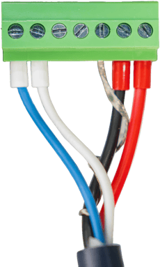
Before starting, connect the Measurand ShapeArray (SAA) to the Loadsensing digital datalogger as shown below.
1. Download and install the Worldsensing app
a. Download the Worldsensing app from the Google Play Store.
b. Once installation is complete, open the app.
2. Connect to the Loadsensing datalogger
a. Use a USB cable to connect your Android mobile device to the Loadsensing digital datalogger.
b. Confirm that the app displays the correct Node ID.
3. Set the time and check for updates
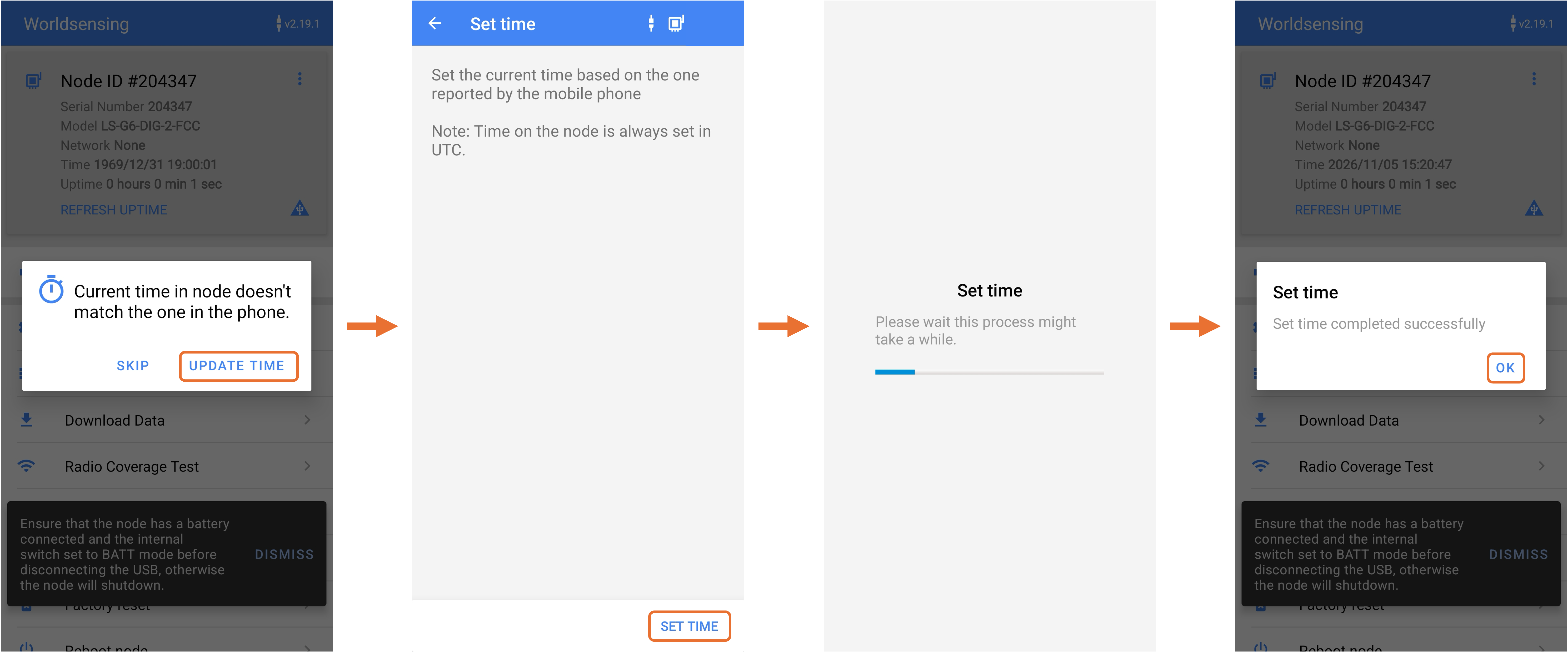
a. If the message “Current time in node doesn’t match the one in the phone” appears, select Update Time.
b. Select Set Time, wait for the process to finish, then select OK. The node stores its time in UTC.
c. Select Firmware Update to check for available updates. Install an available update before continuing, or select Skip if no update is required.
4. Start the Setup Wizard and add a location
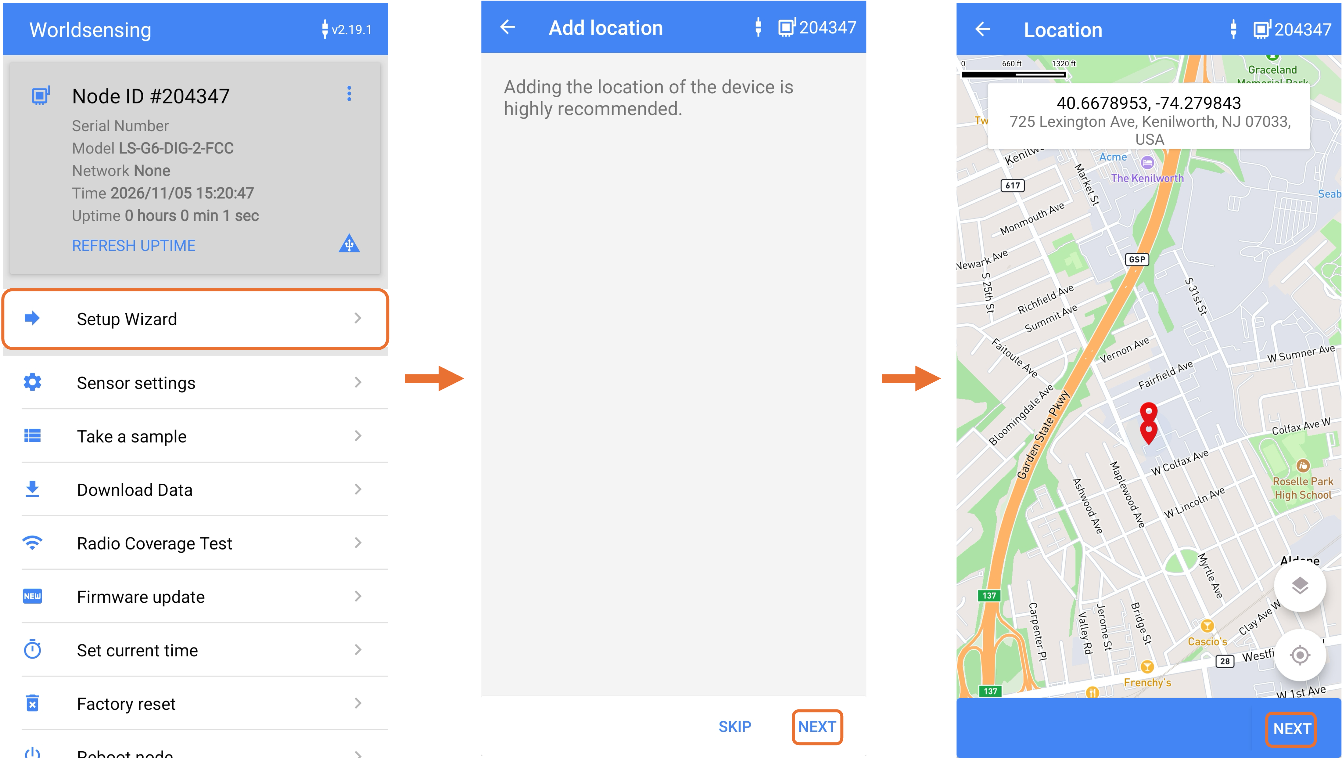
a. Select Setup Wizard from the node menu.
b. On the Add location screen, select Next.
c. Ensure your mobile device is connected to the internet. If prompted, allow location access while using the app or for this session.
d. Confirm the location shown on the map and select Next.
5. Configure the Measurand ShapeArray
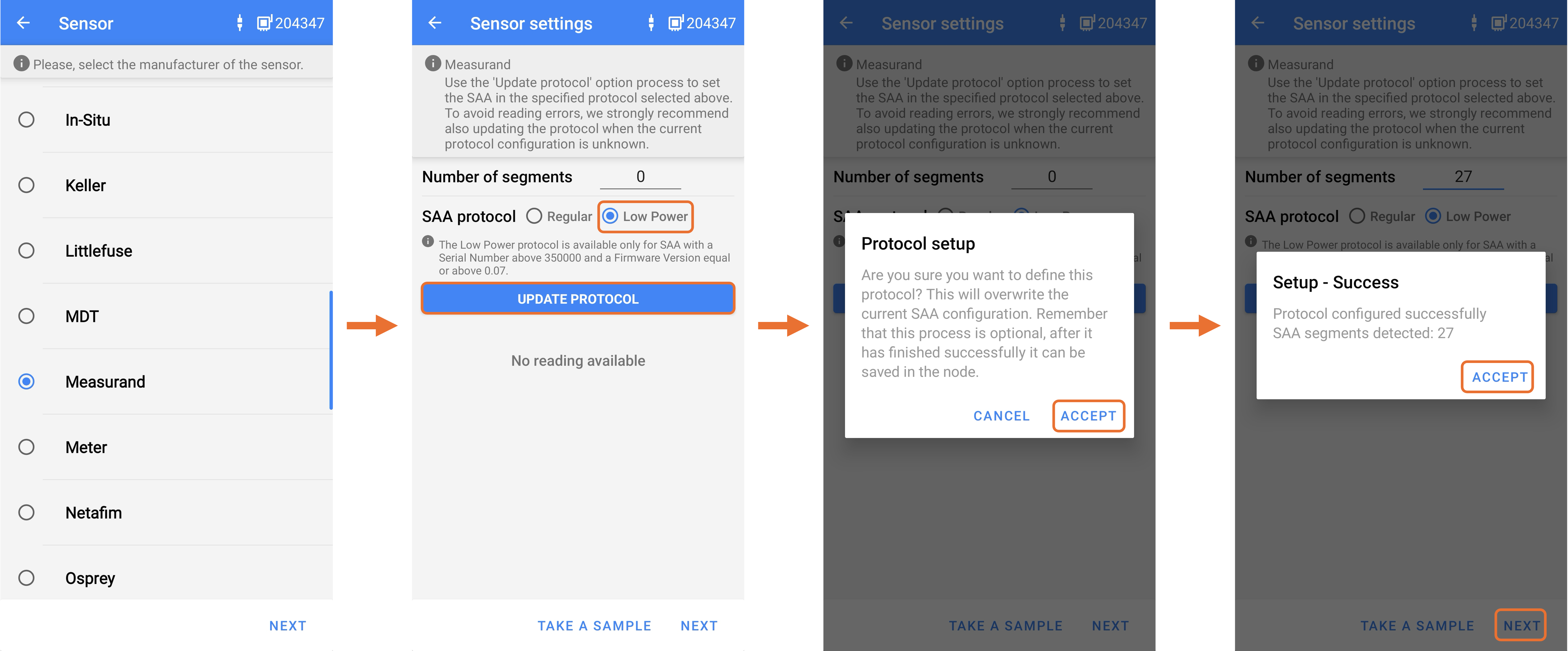
a. On the sensor manufacturer screen, select Measurand, then select Next.
b. In the SAA protocol supported for ShapeArray, select Low Power.
c. Select Update Protocol. Review the prompt and confirm that the segements match the number on the screen, then select Accept to apply the protocol to the SAA. This overwrites the current SAA protocol configuration.
d. When Setup – Success appears, confirm that the detected segment count matches your ShapeArray, then select Accept.
e. Select Next to continue.
Protocol compatibility: The app states that Low Power is available only for an SAA with a serial number above 350000 and firmware version 0.07 or later. Use the protocol appropriate for your sensor. The 27 segments shown below are an example.
6. Perform a sample test
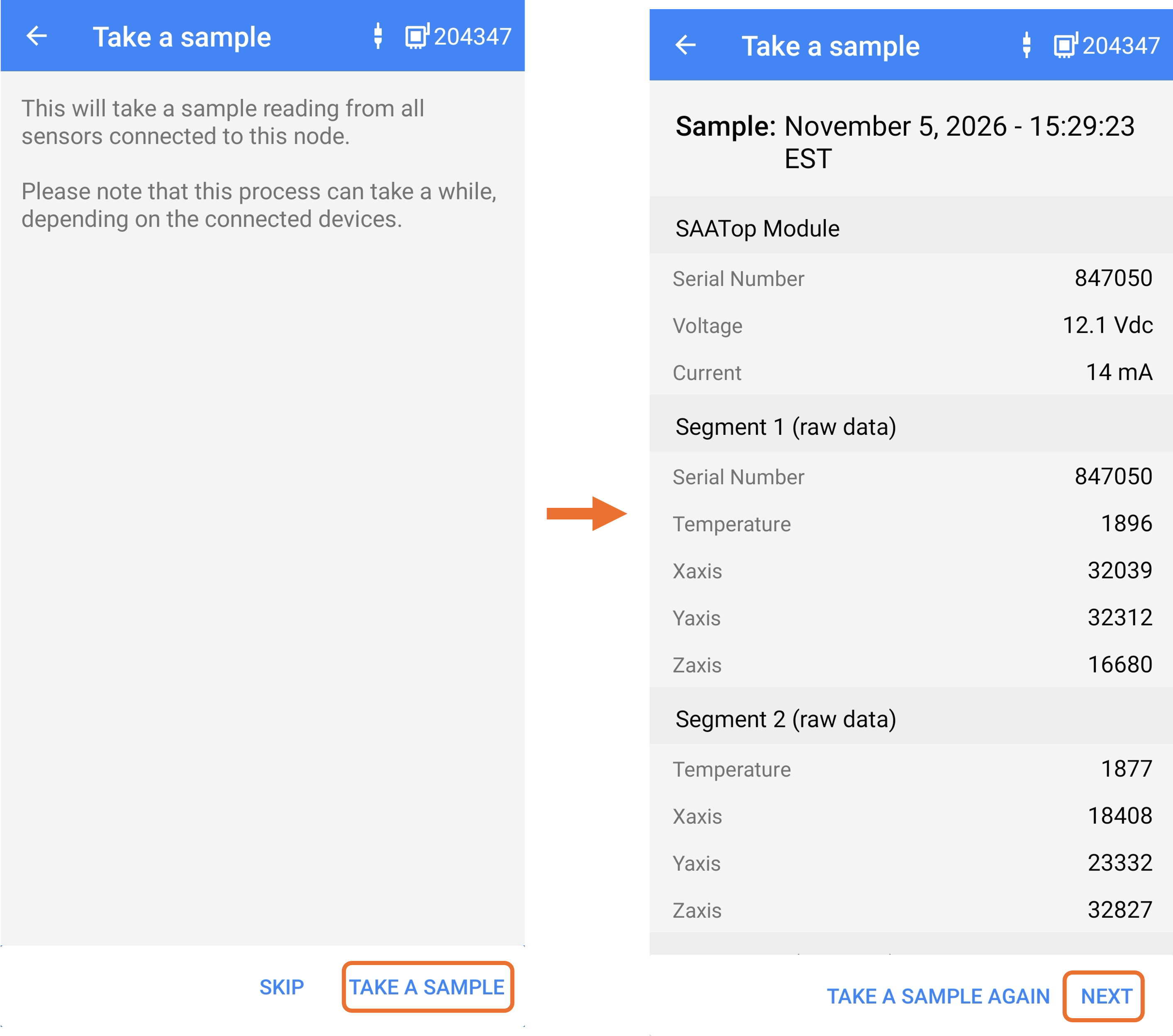
a. Select Take a Sample to read the sensors connected to the node. This process may take a while.
b. Review the SAA information and the segment readings. The values and serial numbers shown below are examples. Confirm that all segments contain valid data.
c. If needed, select Take a Sample Again. Once the readings have been checked, select Next.
7. Sync with Edge
a. If Edge will be used, enter the Edge ID and Password, then select Sync.
b. Otherwise, select Skip.
8. Select the region
a. Choose the appropriate region for the datalogger. In the United States, select FCC.
b. For other regions, choose the corresponding option. Contact Specto Technology Support if you are unsure.
c. Select Next.
9. Configure the CMT Radio
Select one of the two options below.
1. CMT Edge
a. Select CMT Edge Radio, then select Next.
b. Set the Maximum Spreading Factor to the default value of 9.
c. Ensure Channels shows 0 – Freq….
d. Ensure ADR is enabled (blue), then select Next.

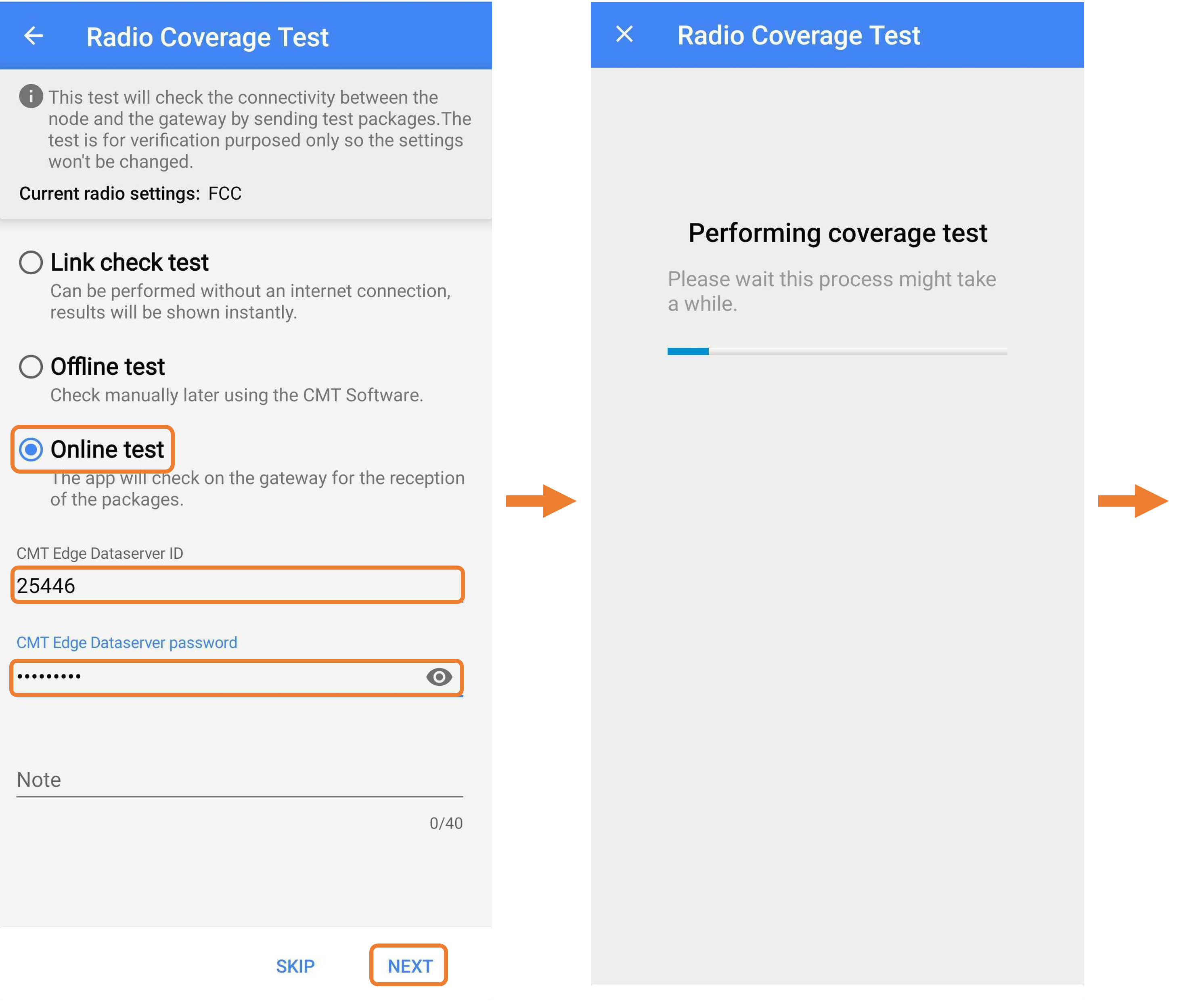
e. Select “Online Test”.
1. If the mobile device or gateway is offline, select “Link Check Test” to verify the connection
f. Enter the Gateway ID for the CMT Edge Dataserver.
g. Enter the Gateway Password for the CMT Edge Dataserver.
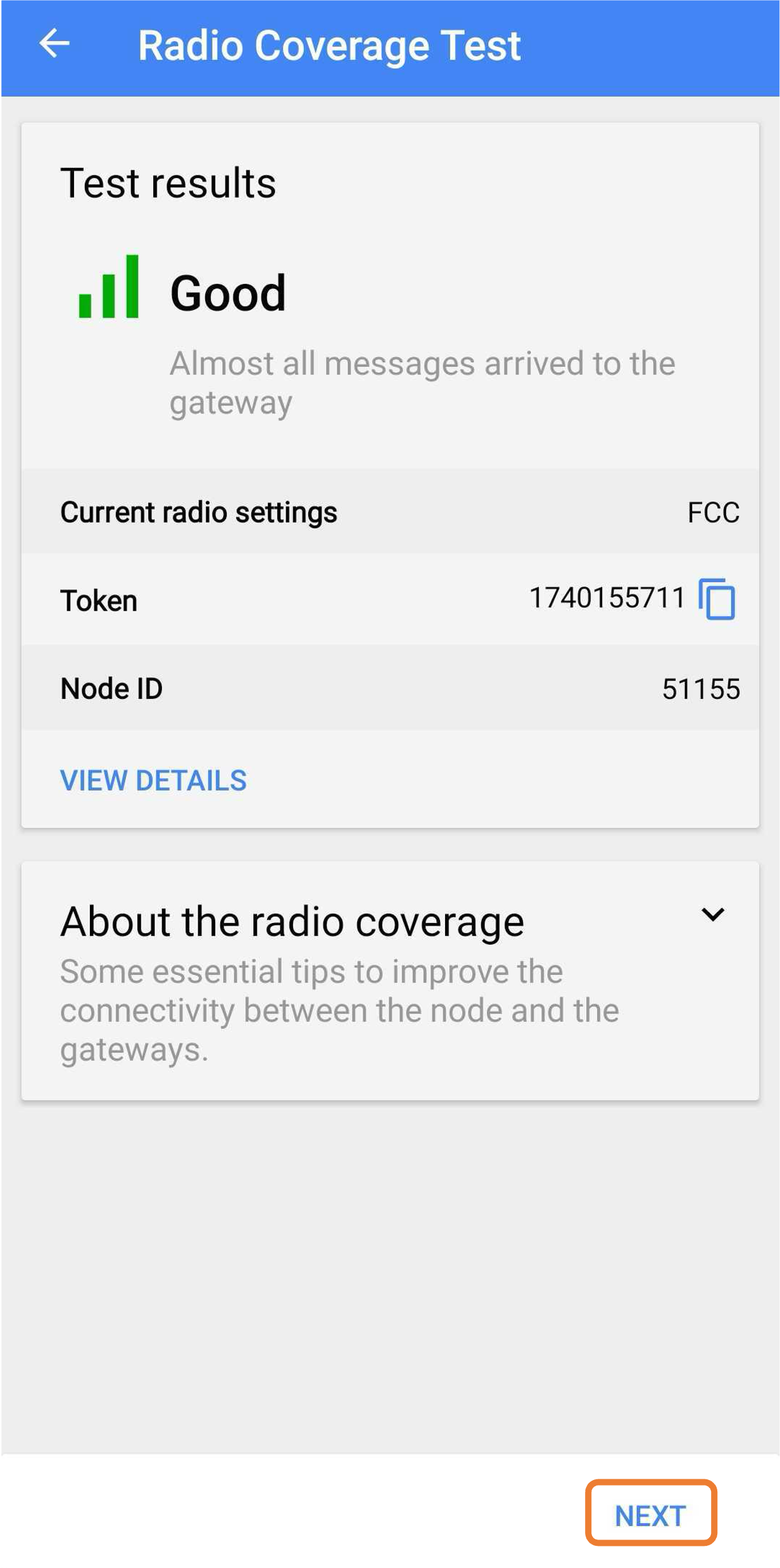
h. Select “Next”.
2. CMT Cloud
a. Select CMT Cloud Radio, then select Next.
b. Set CMT Version to CMT Cloud V2, then select Next.

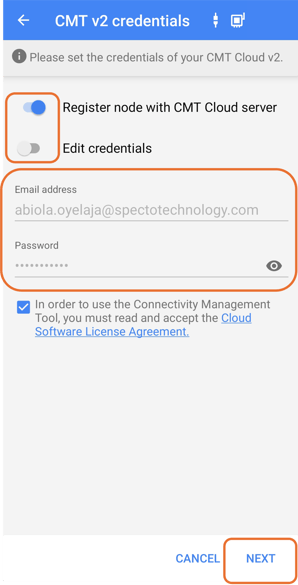
c. Ensure the "Register node with CMT Cloud server" is toggled on.
d. If the credentials under the Email address or Password are incorrect or missing, toggle on "Edit credentials".
e. Select "Next".
10. Complete the gateway and reading settings
a. Choose the maximum number of devices that will connect to the gateway, then select Next.
b. After setup, confirm the gateway reporting period and set the datalogger reading frequency to suit your monitoring requirements.

11. Finish the setup
a. Select Close to finish the Setup Wizard.
b. Before disconnecting USB, ensure the node has a battery connected and the internal switch is set to BATT mode; otherwise, the node will shut down.
